PARAMETERS
- Thrust (F)
- Chamber Pressure (Pc)
- Chamber Temperature (Tc)
- Mixture ratio (r)
- Specific impulse (Isp)
- Universal Gas Constant (R')
- Combustion products molecular weight (𝕸)
- Diameter ratio (Dc/Dt)
- Chamber characteristic length (Lstar)
- Ratio of gas specific heat (ɣ)
- Gravity acceleration (gc)
Once we have the inital data, we can calculate the propellant mass flow rate, this is done by rearranging terms on the specific impulse formula:
1.1
Oxidizer(mo) and fuel(mf) flow rates can be calculated from equations 1.2 and 1.3
1.2
1.3
NOZZLE GEOMETRY
Now we calculate the ratio between throat area and exit area.
2.2
2.2
The Temperature at the throat is given by the following equation:
2.3
The ideal exit velocity is now calculated with the thrust formula:
2.4
Now is the moment to calculate the throat area. Knowing At will allow us to calculate Ae using the ratio calculated before.
2.5
Once that both At and Ae are known, we can calculate their respective diameters using formula 2.6
2.6
CHAMBER SIZING
3.1
Now we are going to determine the chamber area
3.2
3.2
Once we know the volume and the area we can determine the chamber length
3.3
CFD ANALYSIS
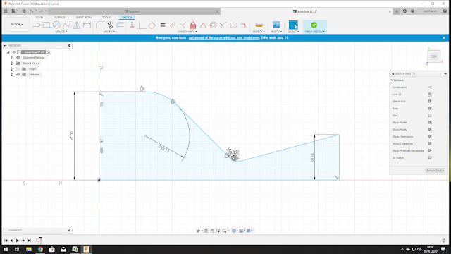
1. Open Fusion360 and create a sketch of the internal flow.
2. Once the sketch is done, click "finish sketch"
4. Import and save the file as a .step
5.Open Autodesk CFD, click NEW and import the model. Once the new project has opened, click in material and then left click on the 3D model to edit material properties.
We are going to set the material to air and the environment conditions to variable.
6. Now it's time to edit the boundary conditions. First we set the outlet as Unknown and the inlet as mass flow rate. We know the mass flow rate from equation 1.1.
7.Click AUTOSIZE and Autodesk CFD will make an automatic mesh.
8.Then click SOLVE, set the number of itinerations. Go to "Solution control" > "Advection" and select Petrov-Galerkin method.
9. Click "Physics" and set the compressibility as "compressible". Set the total temperature of the combustion reaction. Then set the turbulence model to k-epsilon.
10. Click Solve and it will start the analysis. In order to see the results click "Planes"> "Add" and rotate the plane until it matches the profile.


Comments
Post a Comment